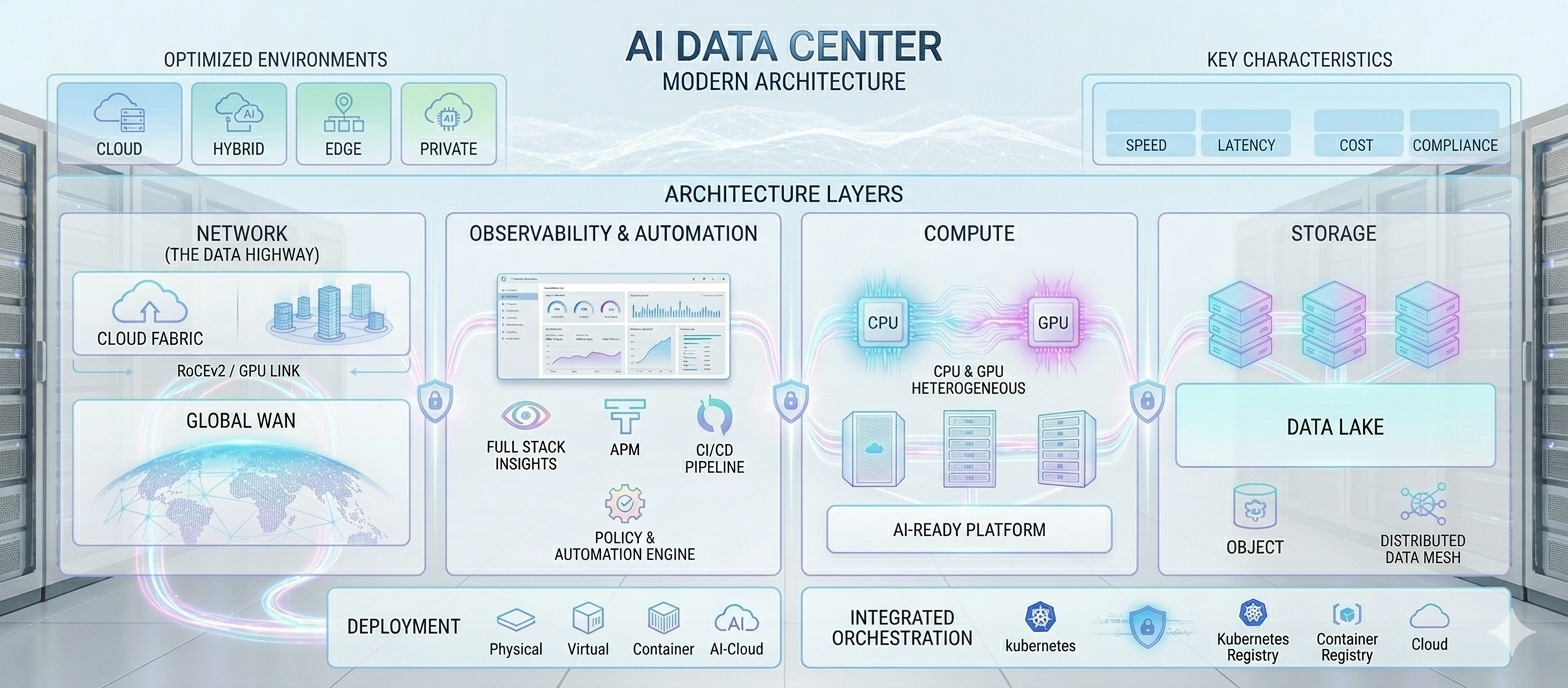
Network for AI Data Center
For many years, the data center network was built for application traffic. Web servers talked to app servers, app servers talked to databases, storage traffic moved in the background, and most flows were independent. Some flows were large and many were small, but the network could usually rely on familiar tools: buffering, TCP backoff, retransmission, ECMP, QoS, and a reasonably oversubscribed leaf-spine fabric.
That design worked because the application was usually above the network. If one flow slowed down, the impact was often local. A user request might take longer, a database call might retry, or a file transfer might finish a little later. The network mattered, but it was not usually part of a tightly synchronized compute loop.
AI changes the relationship. In a training cluster, the GPUs compute for a while and then communicate together. Gradients, activations, or tensor data move across the fabric in repeated phases, and those phases can involve hundreds or thousands of GPUs at the same time. The job behaves less like a collection of servers and more like one distributed machine. When one path slows down, the cost is not just a delayed packet; it can be idle GPU time across the job.
Inference creates a different version of the same problem. A small model served from one GPU may look like a traditional application, but modern large-model inference often spans multiple GPUs or multiple nodes. Tensor parallelism, pipeline parallelism, retrieval, KV-cache movement, batching, and high fan-out service calls can make the network visible to the user as latency. In training, a bad network wastes expensive compute. In inference, a bad network shows up as slow tokens, high tail latency, and lower request throughput.
That is the shift to AI data center networking. The goal is no longer only to connect servers reliably. The goal is to keep GPUs busy during training and keep inference latency predictable, while handling traffic that is synchronized, bursty, bandwidth-heavy, and much less tolerant of packet loss.
The visual comparison below captures where the behavior changes and why AI fabrics need different remediation techniques.
The Shift to AI Data Center Networking: From Independent Flows to GPU Fabrics.
Traditional applications can often tolerate independent flows, localized latency, and TCP recovery. AI training clusters are different: synchronized GPU collectives, heavy east-west transfers, microbursts, and low loss tolerance make the network a direct limiter of GPU utilization.
| Characteristic | AI Data Center Traffic | AI DC Remediation | AI DC Techniques / Terminology | Normal Data Center Traffic | Normal DC Remediation | Normal DC Techniques |
|---|---|---|---|---|---|---|
| SynchronizationLockstep movement | Thousands of GPUs communicate together; one slow path or GPU can stall the phase | Congestion-aware traffic spreading and locality optimization | Adaptive RoutingRail OptimizationTopology-Aware Scheduling |
Mostly independent flows | Standard load balancing | ECMP |
| IncastMany-to-one pressure | Many senders target one receiver simultaneously | Queue protection and early congestion signaling | ECN/DCQCNPFCVOQ |
Smaller-scale incast | TCP-based congestion handling | TCP Congestion Control |
| Elephant FlowsLarge long-running transfers | Long-lived high-bandwidth tensor transfers | Dynamic flow distribution across multiple paths | Flowlet SwitchingAdaptive ECMPDynamic Load Balancing |
Mixed small, medium, and shorter-lived flows | QoS, traffic engineering, and static multipath routing | QoSECMP |
| Communication PatternCollective operations | Collective communication such as all-reduce and all-gather | Optimize collective operations | NCCLSHARP |
Client-server and request-response | Standard routing | TCP/IP Routing |
| Traffic Burst PatternIteration bursts | Iteration-based synchronized bursts | Burst-aware congestion management | Telemetry-Driven BalancingECN |
Random bursts | TCP backoff and buffering | TCP Windowing |
| Bandwidth UsageNear line rate | Sustained near line-rate | Non-blocking fabric design | Clos/Fat-treeMulti-Rail FabricsInfiniBandSpectrum-X |
Variable utilization | Moderate oversubscription | Leaf-Spine |
| Fabric TopologyCluster layout | Topology directly affects collective completion time and congestion hotspots | Use low-diameter, high-bisection, rail-aware, or non-blocking fabric layouts | Dragonfly3-plyFat-treeRail-Optimized Fabric |
Usually leaf-spine or traditional multi-tier enterprise fabric | Scale capacity through predictable oversubscription and ECMP | Leaf-SpineThree-Tier DC |
| GPU-to-GPU CommunicationEast-west exchange | Massive east-west GPU tensor exchange | High-bandwidth low-latency GPU fabric | NVLinkNVSwitch |
Rare direct server-to-server communication | Ethernet switching | PCIeEthernet |
| Congestion BehaviorHotspots | Rapid hotspot formation | Dynamic congestion avoidance | Adaptive Routing |
Distributed congestion | TCP congestion response | TCP AIMD |
| Packet Loss ToleranceLow-loss design | Very low tolerance | Lossless Ethernet transport | PFCETSECN/DCQCNRoCEv2InfiniBand |
More tolerant | Packet retransmission | TCP Retransmission |
| Queue BehaviorMicrobursts | Heavy microbursts and queue buildup | Queue isolation and deep buffering | VOQECN/DCQCNDeep Buffers |
Moderate queue pressure | Shared buffering | FIFO Queues |
| Load Balancing NeedPath adaptation | Requires congestion-aware balancing | Real-time path adaptation | Adaptive ECMPFlowlet Switching |
Static distribution sufficient | Static hashing | ECMP Hashing |
| Traffic PredictabilityRepeating phases | Repetitive iteration patterns | AI-aware workload placement | Topology Aware Job SchedulingKubernetes Affinity |
Random workload behavior | Generic orchestration | Standard Scheduling |
| Scale-Up NetworkingInside the node | Extremely high intra-node GPU bandwidth required | GPU fabric acceleration | NVLinkNVSwitch |
Limited intra-server acceleration | Standard server architecture | PCIe |
| Scale-Out NetworkingAcross nodes | Multi-node GPU cluster communication | High-speed low-latency AI fabric | InfiniBandRoCEv2 EthernetSpectrum-X |
Standard DC interconnect | Enterprise Ethernet | Leaf-Spine Ethernet |
| Performance GoalCluster efficiency | Minimize GPU idle time | Optimize collective completion time | NCCL OptimizationSHARP |
App responsiveness | Throughput optimization | Load Balancers |
The Problem Statement
The problem with reusing a traditional data center network for AI is not that Ethernet, ECMP, or leaf-spine are bad ideas. The problem is that traditional assumptions can become wrong. Oversubscription that was acceptable for web workloads can become a bottleneck when many GPUs need to exchange training data at the same time. Static hashing that was fine for mixed application flows can place large tensor transfers on the same path. Packet drops that TCP could recover from can damage the performance of RDMA traffic. Queues that were tolerable for background traffic can become visible as GPU idle time or inference tail latency.
This is why AI networking cannot be treated as a simple capacity upgrade; it is more about a change in the traffic pattern. A training iteration may look quiet while GPUs are busy, and then suddenly the fabric sees a wave: many senders become active together, the same paths and queues are stressed together, and the slowest part of the exchange can hold back the next compute phase. This is why AI networking feels different from normal application networking. The traffic is synchronous.
That synchronization is what makes incast so important. During a collective operation, many GPUs may send toward the same receiver, aggregation point, or congested output queue. A traditional network might wait for TCP to detect loss and back off, but AI traffic often cannot afford that delay. This is where DCB, or Data Center Bridging, enters the discussion. DCB enhances traditional Ethernet to create a lossless, high-performance network fabric. It helped Ethernet move toward a converged LAN/SAN model, where normal application traffic, storage-style traffic, and RDMA traffic can share the same physical fabric while still receiving different treatment.
- PFC (Priority Flow Control): Classic Ethernet PAUSE pauses the entire link. That is dangerous because one congested traffic type can block everything. PFC improves this by pausing only specific priority classes. At first it can look like
QoSbecause it uses traffic priorities, but it is different. QoS usually decides how traffic is classified, queued, scheduled, or dropped. PFC works at the data link layer and sends a pause signal for a specific traffic class on a local hop. That makes it fast and hop-by-hop, and it can pause the RDMA or lossless class. - ETS, or Enhanced Transmission Selection, assigns bandwidth shares to traffic classes so one class does not consume the link unfairly when LAN, storage, and RDMA traffic coexist.
- DCBX, or Data Center Bridging Exchange, is an extension of
LLDP. It lets neighboring devices exchange DCB settings such as priority groups and PFC configuration, reducing the risk of mismatched lossless-class behavior between a server NIC and switch. - DCQCN / ECN combines congestion marking and rate control for RoCEv2. Unlike PFC, ECN does not send pause frames. It marks traffic at the network layer when congestion is building, and DCQCN uses those marks to slow senders before queues become dangerous. Because this feedback depends on marked packets returning through the control loop, it is more affected by round-trip time than local PFC pause behavior.
Scenario 1: Leaf-to-Spine Uplink Congestion
When several GPU flows leave the same leaf at the same time, static hashing can place too many of them on one spine-facing uplink. One uplink becomes hot while other equal-cost uplinks still have usable capacity.
Scenario 2: Spine-to-Leaf Downlink Congestion
The reverse can happen when flows from different source leaves are all headed toward the same destination leaf. Each ingress leaf may choose a path independently, so the final spine-to-leaf downlink can fill even when the rest of the fabric has spare bandwidth.
Once the burst begins, the pressure moves from queues to paths. AI jobs create elephant flows (large, long-lived packets) because tensors, gradients, and model data are large. A static ECMP hash can accidentally place several large transfers on the same path while another equal-cost path sits underused. Adaptive ECMP improves this by using congestion or telemetry signals instead of relying only on a hash. Flowlet switching is more careful still: it moves traffic at burst boundaries, after a small idle gap, instead of spraying every packet independently. That difference matters because packet spraying can create reordering, while flowlet switching tries to preserve order by keeping each burst together.
The same problem becomes more visible when flows last longer. A long-lived AI transfer pinned to a poor path can waste bandwidth for an entire phase of the job. DLB, or Dynamic Load Balancing, is Cisco's congestion-aware enhancement to ECMP. It is one practical way to achieve adaptive path selection in AI fabrics by steering flowlets toward healthier links instead of relying only on static hashing. This is why AI fabric conversations keep returning to adaptive routing, flowlets, telemetry, and congestion-aware balancing. The workload is too synchronized, and the GPUs are too expensive, to leave path selection entirely to static hashing.
As the cluster grows, the conversation shifts from individual flows to the shape of the fabric itself. In a normal data center, moderate oversubscription may be acceptable because not every workload peaks at the same time. In AI training, many GPUs can demand bandwidth at the same time by design, so the Ethernet fabric often has to move toward 400 Gbps and 800 Gbps links instead of older 25/100 Gbps assumptions. Clos and fat-tree fabrics provide predictable bisection bandwidth. 3-ply describes a three-layer network with a super-spine layer, and is recommended for Intel Gaudi designs. Dragonfly becomes useful at larger scale because it lowers network diameter through strong group-to-group connectivity. Rail-optimized designs matter when servers have multiple NICs or GPU rails and the network needs to keep traffic aligned with the physical layout. In this model, a GPU or GPU rail is pinned toward a specific leaf path, which helps avoid unnecessary cross-rail movement and reduces avoidable hotspots.
The reason this topology work matters is GPU-to-GPU communication. Inside a node, NVLink and NVSwitch move data between GPUs at very high bandwidth. Once the job crosses server boundaries, the scale-out fabric has to provide the closest possible experience: low latency, high throughput, low loss, and predictable path behavior. If that fabric is weak, GPUs wait. In training, waiting shows up as lower cluster utilization. In inference, waiting shows up as slower tokens, worse tail latency, and lower request throughput.
At that point the design often becomes a choice between Ethernet-based RDMA and a purpose-built cluster fabric with InfiniBand. RoCEv2 brings RDMA semantics to Ethernet, which makes it attractive when a team wants Ethernet economics, Ethernet operations, and integration with the broader data center. But RoCEv2 should not be treated like ordinary best-effort Ethernet. It needs disciplined QoS, PFC, ECN, congestion control, and careful telemetry. When those pieces are operated well, RoCEv2 can support high-performance AI fabrics while staying in the Ethernet ecosystem.
InfiniBand starts from a different place. It is built as a high-performance cluster fabric, so it is often chosen when the environment is performance-first, tightly controlled, and designed around large training jobs. The operational model can be more specialized than Ethernet, but the fabric behavior maps naturally to low-latency, RDMA-heavy AI and HPC communication.
Fabric Choice: InfiniBand, Spectrum-X, or Enterprise Ethernet
| Fabric | Pros | Cons |
|---|---|---|
| InfiniBand | Built for HPC and AI cluster communication from the start. It gives strong RDMA behavior, low latency, high throughput, and predictable performance for tightly coupled training jobs where many GPUs communicate together. |
The operating model is more specialized than normal Ethernet. Teams may need separate skills, tools, cabling choices, and lifecycle processes, and the fabric can feel less natural for environments that want one common enterprise network model. In practice, many modern AI deployments also tie the design closely to the NVIDIA ecosystem. |
| Spectrum-X | NVIDIA Spectrum-X keeps the Ethernet direction but makes it more AI-specific, combining Spectrum Ethernet switches, SuperNICs, congestion control, telemetry, and adaptive behavior for more predictable RoCE-based GPU fabrics. |
It should not be treated like generic Ethernet. The value comes from a more coordinated platform, so hardware choice, NIC behavior, software, telemetry, and RoCE/DCB configuration all matter. Poor tuning can still expose loss, queuing, or path imbalance. It is also closely tied to the NVIDIA ecosystem, which can create vendor lock-in for teams that want a more open Ethernet supply chain. |
| Enterprise Ethernet | Familiar, broadly interoperable, and easy to integrate with existing data center operations. It works well for conventional application traffic, storage access, management traffic, and smaller AI environments that are not dominated by synchronized GPU exchange. |
A default leaf-spine Ethernet design is often too best-effort for large AI training. Static ECMP, oversubscription, normal buffering, and ordinary TCP recovery can leave GPUs waiting unless the fabric is redesigned with lossless classes, ECN, PFC, telemetry, and congestion-aware balancing. |
Inference adds another twist. If a model is served from one GPU or one server, the network may mostly carry user requests, retrieval calls, storage access, or service-to-service traffic. A traditional Ethernet design may be enough. But when inference scales into multi-GPU or multi-node serving, the network starts to affect token latency, batching efficiency, cache movement, and tail behavior. The same fabric ideas return: avoid incast, reduce hot paths, protect RDMA traffic when it is used, and design topology for predictable east-west movement.
The practical rule is to match the network to the communication pattern. Use NVLink and NVSwitch for scale-up GPU communication inside a server or tightly coupled system. Use RoCEv2 when Ethernet integration matters and the team can operate a tuned lossless fabric. Use InfiniBand when the cluster is built primarily for high-performance AI or HPC communication. Use Clos, 3-ply, Dragonfly, fat-tree, and rail-optimized layouts when the problem is not just connecting nodes, but keeping synchronized GPU communication predictable at scale.
That is the larger shift from traditional networking that connected applications. AI data center networking has to support the communication pattern of the workload itself: synchronized training phases, bursty inference paths, long tensor transfers, RDMA traffic, topology-aware scheduling, and GPU-to-GPU movement. The network is still transport, but in AI it also becomes a performance boundary.
Leave a comment
Questions, corrections or ideas are welcome. Your message goes privately to the author by email. It is not shown on this page.